in-Situ Pressuremeter
Zhuozhou Tianpeng Imp. & Exp. Trade Co., Ltd.- Type:Strength Testing Machine
- Maxcapacity:5.5MP
- Accuracy Grade:0.5
- Load Way:Mechanical Load
- Loading Method:Static Load
- Display:Digital
Base Info
- Model NO.:PY-5
- Control:Manual Control
- Weight:100-500Kg
- Power Source:No
- Oil Cylinder Position:No
- Min.Reading of Pressure Gauge:0.005MPa
- Original Volume of Pressuremeter Chamber:491 Cm3
- Required Borehole Dia.:Dia. 52~Dia. 58mm
- Test Length:250mm
- Length:500mm
- Transport Package:Stardard Export Package
- Trademark:C-TECH
- Origin:China Mainland
- HS Code:90248000
- Production Capacity:500sets,Month
Description
Basic Info.
Model NO. PY-5 Control Manual Control Weight 100-500Kg Power Source No Oil Cylinder Position No Min.Reading of Pressure Gauge 0.005MPa Original Volume of Pressuremeter Chamber 491 Cm3 Required Borehole Dia. Dia. 52~Dia. 58mm Test Length 250mm Length 500mm Transport Package Stardard Export Package Trademark C-TECH Origin China Mainland HS Code 90248000 Production Capacity 500sets/MonthProduct Description
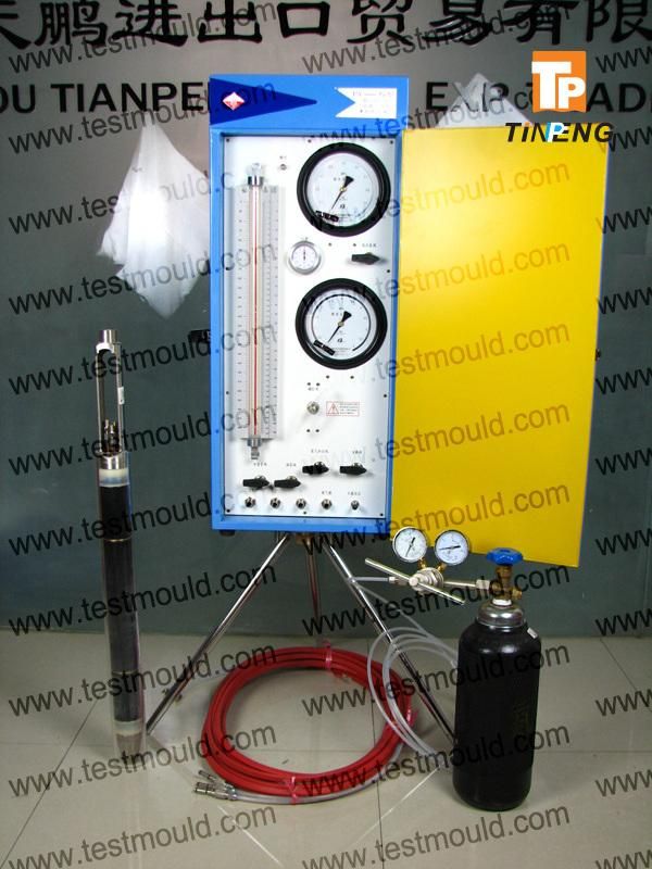
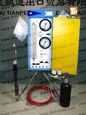
In-situ PressuremeterModel PY Field Pressuremeter
Control Unit (C.U.), tubings and 3-cells probe to perform in situ
Pressuremeter test in soils conform to the ISO 22476-4 and ASTM D-4719-00 Standards.
The pressuremeter test is an in-situ testing method used to achieve a quick measure of the in-situ stress-strain
relationship of the soil. In principle, the pressuremeter test is performed by applying pressure to the sidewalls of a borehole and observing the corresponding deformation.
The pressuremeter consists of two parts, the read-out unit which rests on the ground surface, and the probe that is inserted into the borehole (ground). The original Ménard-type pressuremeter was designed to be lowered into a performed hole and to apply uniform pressure to the borehole walls by means of infl atable fl exible membrane.
As the pressure increases, the borehole walls deform. The pressure is held constant for a given period and the
increase in volume required for maintaining the constant pressure is recorded. A load-deformation diagram and
soil characteristics can be deduced by measurement of the applied pressure and change in the volume of the
expanding membrane.
From the test readings (volume variation based on controlled pressure), a stress-strain curve can be obtained,
in the case of plane deformation, which yields :
-the Ménard Pressuremeter modulus
- the creep pressure
- the Menard limit pressure
Main Components
| The Control Unit | Equipped with devices to precisely regulate the pressure applied to the probe and to read its volume changes with pressure increments and time. A nitrogen cylinder provides the pressure source. The box stands on a tripod. |
| The plastic tubing | This coaxial or twin tubing, fl exible, high resistance with small dilatation, connects the probe to the monitoring box. |
| The 3-cell probe | It includes a central measuring cell, fi lled with water. Its volume changes are read on the Control Unit volumeter. The probe is totally protected by a rubber cover (different types regarding soils stiffness) which is inflated by the gas to form the 2 guard cells. Pressures applied to the 3 cells are balanced through the differential pressure regulator to ensure a true cylindrical deformation along the measuring cell. |