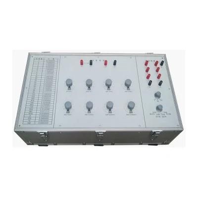
GDB-GD Transformer Turns Ratio Verification Device TTR Meter Calibrator
HV Hipot Electric Co., Ltd.- Type:Universal Testing Machine
- Accuracy Grade:0.5
- Load Way:Electronic Load
- Loading Method:Dynamic Load
- Display:Digital
- Control:Computer Control
Base Info
- Model NO.:GDB-GD
- Weight:0-100Kg
- Power Source:AC220V
- Accuracy level:0.001 class
- Rated input voltage:0-600V
- Rated frequency:50Hz
- Design variable ratio test range:1 ~ 10000
- Transport Package:Standard Export Wooden Box
- Specification:ISO, SGS
- Trademark:HV Hipot
- Origin:Wuhan, China
- Production Capacity:5000set,Year
Description
Basic Info.
Model NO. GDB-GD Weight 0-100Kg Power Source AC220V Accuracy level 0.001 class Rated input voltage 0-600V Rated frequency 50Hz Design variable ratio test range 1 ~ 10000 Transport Package Standard Export Wooden Box Specification ISO, SGS Trademark HV Hipot Origin Wuhan, China Production Capacity 5000set/YearProduct Description
GDB-GD Transformer Turns Ratio Verification Device TTR Meter CalibratorDescription
The transformer turns ratio verification device adopts high-nickel permalloy as the magnetic conductive material, and is made of high-strength polyester enamelled copper round wires that are evenly arranged, and the structure is reasonable and reliable.
It is mainly used to verify various transformer ratio bridges, it can not only verify the error of single phase but also verify the connection group. The equipment has high accuracy and a wide range of design transformation ratio tests, and is suitable for verifying various transformer ratio bridges. In addition, the device can also be used as a high-precision induction voltage divider. When verifying the transformer ratio error, the single-phase calibration cannot fully reflect the correctness of the internal wiring of each switch. Per the requirements of the standard IEC74-4, after verifying the error, the bridge must also be verified with actual three-phase transformers of various connection methods. Therefore, the device is designed with a three-phase combined voltage transformer. The instrument consists of three precision voltage transformers, which are switched into actual three-phase transformers with various wiring methods through switches, and have multiple turns ratios. The equipment has high accuracy, small size, light weight and easy to use.
Technical Specifications
Use Condition
- The ambient temperature is + 5ºC-+ 40ºC
2. The distortion coefficient of the power waveform is not more than 5%
The frequency variation range is within 50 ± 0.5Hz.
3. There are no harmful gases and other media that seriously affect the insulation of the voltage transformer at the place of use.
4. There is no serious vibration and bumps in the place of use.
5. The place of use should not have strong external electromagnetic fields not related to work.
Parameters
| Accuracy level | 0.001 class |
| Rated input voltage | 0-600V |
| Output voltage | 0~555.55555V (or 0~50V) |
| Rated frequency | 50Hz |
| Design variable ratio test range | 1 ~ 10000 |
| Insulation strength | 2.5KV withstand voltage for 3 minutes, insulation resistance ≥50MΩ |
| Connection group | Y / Y0, Y / Y6, D / D0, D / D6, Y / D11, Y / D5, D / Y11, D / Y5 |
Attention
1. When verifying the transformation ratio error of the transformer ratio bridge in the single-phase state, only the voltage divider part of the verification device can be used. The input voltage terminal buttons of the voltage divider are A and X, the maximum input voltage is 600V, and the output voltage terminal buttons are a and x. By adjusting the output voltage, different turns ratios can be obtained.
2. When verifying the connection group of the transformer ratio bridge under three-phase state, the primary voltage terminal buttons are A, B, C, and the secondary voltage terminal buttons are a, b, c, adjust the group switch combination, then get different connection groups.
3. When the device is used as an inductive voltage divider to detect high-voltage voltage transformers with certain special voltage ratios, it needs to be verified with conventional standard voltage transformers.
4. When wiring, pay attention to the polarity and ground point, and keep good contact.
5. During the use of the transfer switch of the inductive voltage divider, please do not use excessive force to switch to avoid damage to the switch.
6. When power on, secondary short circuit is strictly prohibited, and the power must be cut off every time the wiring or voltage ratio changing .
7. During transportation and storage, wind, rain, inversion and shock should be prevented.
8. For the safety of the equipment, when the instrument is in use, the maximum voltage at its input terminal should not exceed 1.5 times the rated voltage.