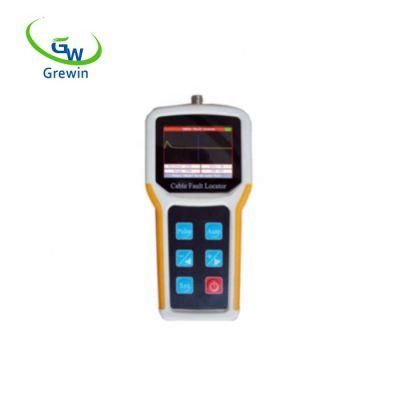
Color LCD Handheld Tdr Cable Fault Locator Under Sunshine 8km
Tianjin Grewin Technology Co., Ltd.- Test Mode:Instant Test
- Usage:Network Cable Tester, Audio Cable Tester, Coaxial Cable Tester, Digital Cable Tester
Base Info
- Model NO.:TDRL-902
- Test Region:Unformed
- Cable Type:Power
- Power:Electricity
- Certification:CE, RoHS
- Customized:Customized
- Color:Orange
- Name:Tdrl-902 Tdr Cable Fault Locator
- Range:0-8km,16km,32km
- Resolution:Max.1m
- Unipolarity Impulse:30V
- Measurement Dead Zone:1m
- Display:128*64 DOT LCD
- Dimension:225mmx105mmx50mm
- Weight:0.5kg
- Transport Package:Export Standard Cartons with Strong Pallets
- Specification:CE ROHS
- Trademark:grewin
- Origin:China
- HS Code:850450000
- Production Capacity:50000 PCS ,Week
Description
Basic Info.
Model NO. TDRL-902 Test Region Unformed Cable Type Power Power Electricity Certification CE, RoHS Customized Customized Color Orange Name Tdrl-902 Tdr Cable Fault Locator Range 0-8km,16km,32km Resolution Max.1m Unipolarity Impulse 30V Measurement Dead Zone 1m Display 128*64 DOT LCD Dimension 225mmx105mmx50mm Weight 0.5kg Transport Package Export Standard Cartons with Strong Pallets Specification CE ROHS Trademark grewin Origin China HS Code 850450000 Production Capacity 50000 PCS /WeekProduct Description
Name: 0-8km visual Cable Fault Locator Power Meter
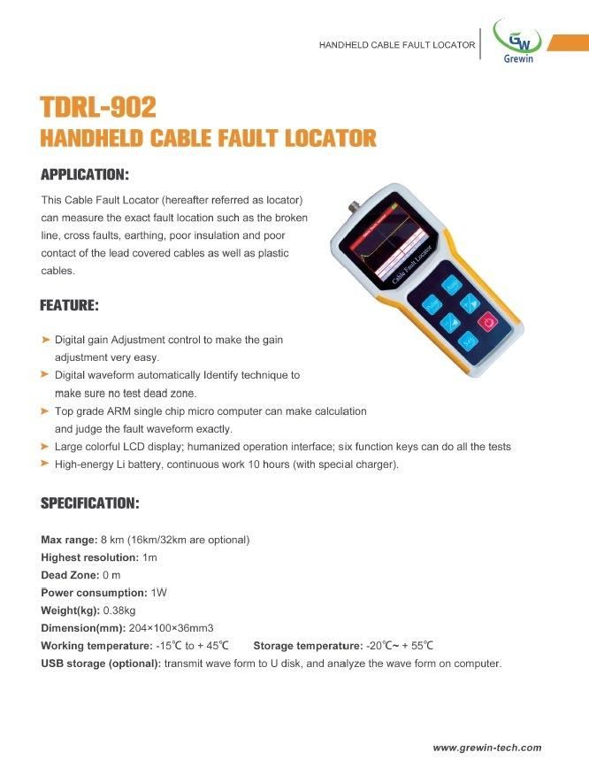
The highlights for this locator are that it can test numbers of typical faults, features are as follow:
- Digital gain Adjustment control to make the gain adjustment very easy.
- Digital waveform automatically Identify technique to make sure no test dead zone.
- Top grade ARM single chip micro computer can make calculation and judge the fault waveform exactly.
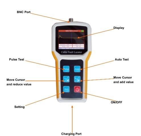
- Large colorful LCD display; humanized operation interface; six function keys can do all the tests.
- High-energy Li battery, continuous work 10 hours (with special charger).
SPECIFICATIONS
- Max range: 8 km (16km/32km are optional)
- Highest resolution: 1m
- Dead Zone: 0 m
- Power consumption: 1W
- Weight(kg): 0.38kg
- Dimension(mm): 204×100×36mm3
- Working temperature: -15ºC to + 45ºC
Storage temperature: -20ºC~ + 55ºC
USB storage (optional): transmit wave form to U disk, and analyze the wave form on computer
WORKING PRINCIPLE
Pulse testing is a kind of remote testing method; one can locate the fault point without testing on the field or testing with end-to-end coordination. The principle of the theory is:
The instrument emits a pulse to the line, when the line has faults, the pulse reflection will change. If the come and back time can be measured, the location of the fault point can be detected.
Suppose the pulse transmission velocity in electric cable velocity is V, the come and back time that the pulse travels between the test point and the fault point is T, the fault distance is L, then:
- 2L = V T
- L = V T/2
For example, the sending end transmits a pulse to the cable, after 20μs, the sending end get the reflection pulse. If the pulse transmission velocity in the electric cable is 201m/μs, the fault distance L is
L = 201×20/2 = 2010m
TESTING PROCEDURES
Diagnosis of fault characters
To insure the accuracy of the testing of fault point, the testing personnel shall diagnose the fault characters correctly and then choose the most suitable testing mode. The characters of telecom cable faults can be simply divided into the following several kinds:
Broken line
One or many cable core line are broken.
Crossed line
The insulating resistance between the different couple of lines drops and causes the communication amplitude drops.
Earthing fault
The insulating resistance between the core line to the lead cover drops and causes low communication quality
Crosstalk noise
When the cable core insulation material is invaded by water or humidity, the insulating resistance will drop and cause low communication quality or even blocks.
Bad insulation
The insulating resistance between different couple of lines and the core drops to a very low level, the communication quality comes under serious influences.
Fault Testing
Cut off the cable to be tested both sides lines or equipment. Make sure the cable to be tested is free of voltage. Using this instrument to do intelligence testing first, if the fault cannot be detected and then you can change to manual testing.
Locating fault point
The tester will Judge the approximate location based on the testing result, then check the cable, cable gland, cross boxes, etc., depending on the actual situation.
AUTO TEST
Press, connect the testing lead line and fault cable line. Press and then the instrument will show the testing result.
Note: The default setting wave velocity is 200m/ μ s, when you perform intelligence testing, the user shall check whether need to adjust the velocity.
MANUAL TEST
The relevant setting and parameters will demonstrate on the underneath of the display screen. Press to adjust the setting and parameters.
1) Gain
Press , until "Gain" shows reverse color display. Then press or
to adjust the amplitude (1~99 adjustable), Press , the screen will display the wave
after gain adjustment.
2) Range
During manual testing, range decides the maximum testing distance of the instrument, so the range value shall be chose as longer than actual length of the cable to
be tested. To adjust the Range, press , until Range shows reverse color display.
Press or to adjust the Range.
3) VOP
The precision of the wave velocity, directly affect the precision of the testing result. So the wave velocity shall be calibrated according to the cable characters. Press ,
until VOP shows reverse color display. Then, press or to adjust the wave velocity.
Adjust the Range and VOP according to the characters and estimated length of the cable to be tested. Appropriately adjust the wave amplitude to make the waveforms on the display screen to be observed easily. Move the cursor to inflection of the reflected waveform. The fault distance will demonstrate on the underneath of the display screen.
4) Waveform Comparison
Press until it displays "Press "-" to memory, "+" to both". Now press "" to
save the current waveform; press to call the original out and compare with the current waveform.
5) Save File (Optional)
Press until it displays "Press "-" or "+" to enter file mode". Now press
or to enter into file save mode.
File save mode can not only test & save cable but also can check & analyze the original waveform.
Save File
When you choose "Current Test", press to test the current cable. After test is finished, if you want to save file, you can press until "Press "-" to quit, "+" to
save" appears. Under this condition, press to normal testing mode; press to save the current file to U-disk.
Check and analyze the previous wave files
Press until it displays "Press "-" to memory, "+" to both". Now press "" to
save the current waveform; press to call the original out and compare with the
current waveform. When you are interested in any wave files, you can press to analyze the current wave file. Under this mode, you can do some operation of the saved file. And the operation method is same as cable operation method. For detailed operation steps, you can refer to the manual testing chapter
VOP REFERENCE TABLE
| Items | Quantity |
| TDR Cable Fault Locator | 1PCS |
| Test Line | 2 PCS |
| Charger | 1 PCS |
| Carrying Bag | 1 PCS |
| User Manual | 1 PCS |
| CD with management software | 1 PCS (Just for USB function) |
| U-Disk | 1 PCS (Just for USB function) |
CHARGING
Current battery power is showed at the top-right of the screen. If the battery power
is inadequate, please use the instrument charger to charge it.
The indicator light of the charge adapter will be red when charging; and it will turn
green after it's fully charged.
PACKING LIST
| Insulators | signal propagation velocity (m/us) |
| High Polymer | 168-186 |
| Filled polythene | 192 |
| Polythene | 201 |
| Teflon | 213 |
| Paper pulp (0.13uF/Km) | 216 |
| Foamed polyethylene | 246 |
| Paper (0.117uF/Km) | 264 |
| 9.5mm coaxial (w) | 286 |
| 9.5mm coaxial(s) | 295 |
ATTENTIONS
Keep display screen away from direct sunlight. The contrast ratio of LCD will drop
when temperature higher than 60ºC and it will return to normal when temperature is lower
than 60ºC.
Before testing, better measure the voltage of fault cable to be tested, in order to
avoid test errors or damage the instrument
Do not hit LCD screen.
Company introduction
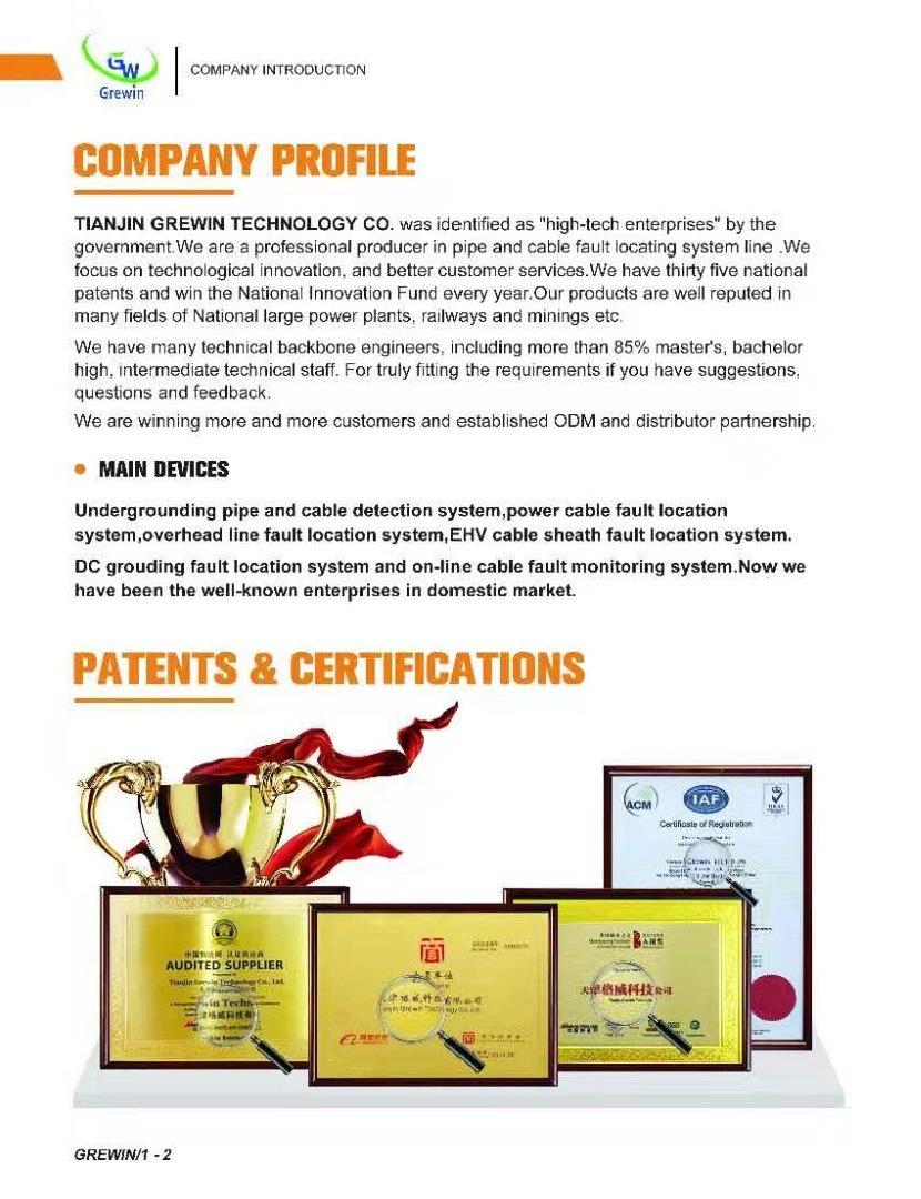
1.certification
We have passed ISO9001:2015,CE,SGS approval and IEC report
2.Company profile
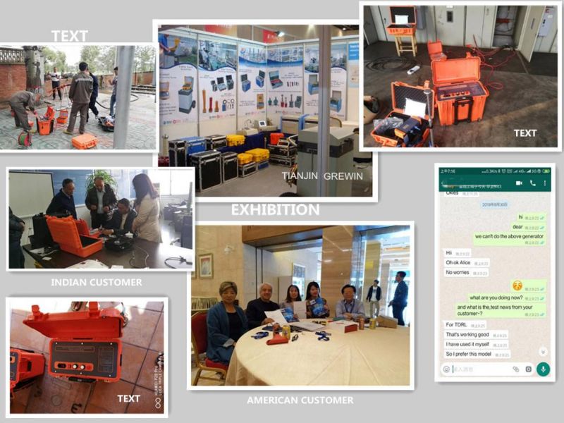
Tianjin Grewin is concentrating on transformers for 20 Years and complianted by ISO9001:2015,CB,IEC CB,CE etc.We're always pay great attention to its business philosophy "Quality and Honesty First".Grewin is specialized in the design and manufacture of wound components such as transformer,current sensors, chokes etc .windely used in communications,electronics,meters,industrial control,medical equipments and other fields.We are also a provider of power meters and instruments locators. 85% of its products exported to America, Europe, and Asia etc.We sincerely invite you to join us to create a bright future.
3.Terms of Shipment:
Within 10 working days after received related prepayment or L/C.
4.Payment terms:
(1)T/T 100% or 50% deposit by T/T in advance, balance amount to be paid 7 days before
delivery.
(2) By irrevocable L/C at sight, to be issued immediately against confirmed order.
(3)Payment by T/T, if order amount is less than USD 20,000.
5.Warranty:
(1)We provide 1 year warranty.
(2)If the product is defective, please notify us within 3 days of delivery.
(3)All products must be returned on their original condition, in order to qualify for a refund or exchange of goods
6.Why choose us?
Quality and honest first!
A. Flexible service for diffierent transformers with high efficiency performance.
B. Over 40 years experience of transformer designing and producing.
C.100% test of every single product we produce from incoming material checking.
D. UL, CE, ISO9001:2008
E. We offer custom-made transformers, OEM and ODM are welcome
F. We deliver the quality you expect at consistently competitive prices
G.Transformer quality lifetime:10 Years.
H.Specialty Sales service:5 -10 Years
7.Flow chart of trading activities:
NO | Step | Days need |
1 | Request for quotation | 1 day |
2 | Making quotations | 1 day |
3 | Offer and counter offer | 3 days |
4 | Sending and receiving samples | 3-10 days |
5 | Sample confirmation | 3 days |
6 | Placing a firm order | 1 day |
7 | Paying and receiving the down payment | 1-4 day |
8 | Factory production & Quality inspection | 15-20 days |
9 | Paying and receiving the balance | 4 days |
10 | Delivery of goods | 1 days |
8.contact
Tianjin Grewin Technology Co.,Ltd.
Web:transformer.en.made-in-china.com
Address: 2# MeiNian Plaza No.16 DongTing Road,Hexi Distr,300222,Tianjin China.