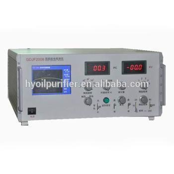
Gdjf-2008 Transformer Partial Discharge Tester Pd Tester Meter
Chongqing Gold Mechanical & Electrical Equipment Co., Ltd.- Usage:Partial Discharge Tester
- Operation Mode:Automatic
- Display:Digital Display
- Test Voltage:100kv
- Warranty Period:1 Year
- Product Name:Partial Discharge Tester
Base Info
- Model NO.:GDJF-2008
- Transport Package:Wooden Case Packing
- Specification:450*450*190 mm
- Trademark:Gold
- Origin:Chongqing
- HS Code:9031809090
- Production Capacity:100PCS,Month
Description
Sensitivity(pC)
Unsymmetrical circuit)
Amplifier band
Low terminal: 10KHZ, 20 KHZ, 40 KHZ (optional)
High terminal: 80 KHZ, 200 KHZ, 300 KHZ (optional)
Amplifier gain adjustment
Coarse control - there are 6 gears for coarse tuning, the gain of each gear is 20±1db
Fine control ≥ 20 db
Time windows
Width of window, adjustable 15o-150o
Window position, adjustable 0o-170o
Two windows can be opened simultaneously or separately
Discharge meter
Digital display
PD display: LED 3½ digits
0-100.0 limit of error <±3% (full scale)
Ellipse time base
Frequency: 50Hz and arbitrary frequency
Elliptic display color is yellow
Elliptic rotation: each gear is 30°, 180 ° rotation can be made.
Display: ellipse - straight line
High frequency time base elliptical input voltage less than 220 V, intake power < 1VA
Waveform lock
Lock required waveform of any time to facilitate observation and analysis
Testing Voltage meter
Range: 100KV (Can be expanded)
Display 31/2 digital voltage meter
Accuracy: better than ±2% (full scale)
Inside, outside the zero mark function
Dimensions: 450×450×190 mm
Weight: about 16kg
Technical Specifications:
The principle is based on ERA i.e high frequency pulse current measuring.
When test object generates partial discharge under testing voltage, the discharge pulse
signals is carried through coupling capacitors Ca into input unit, which gets pulse signals.
After amplification of low noise through preamplifier, the required frequency band chosen by filter amplifier and the main amplifier (reaching the required amplitude and get zero-marked pulse), the discharge pulse can be seen on the ellipse of CRO, and the peak marker also displays on the meter.
Time window controls the working time of pulse peak meter of testing voltage each week,and brightens the corresponding display area in the period of time, which can avoid the interference of the fixed phase.
Test voltage meter produces, through capacitive voltage divider, test voltage zero marker signal, and displays zero marker pulse on CRO. The test voltage is displayed on digital voltage meter.